PCB assembly using stencil and 3D printed jig
Ordering a revision of a power electronics board from Aisler I decided to get a metal paste stencil as well to be able to cleanly solder using the reflow oven.
I already did a first board just taping the board and stencil to the table and applying solder paste. This worked but it is not very handy.
Then I came with the idea to use a 3D printed PCB holder that would ease the process.
The holder
The holder (just a rectangle with a hole) tightly fits the PCB. It is a bit larger then the stencil and 0.1mm less thick then the PCB to make sure the connection between the PCB and the stencil is tight.
I first made some smaller test prints but after 3 revisions the following openSCAD script gave a perfectly fitting PCB holder:
// PCB size
bx = 41;
by = 11.5;
bz = 1.6;

// stencil size (with some margin for tape)
sx = 100; // from 84.5
sy = 120; // from 104

// aisler compensation
board_adj_x = 0.3;
board_adj_y = 0.3;

// 3D printer compensation
printer_adj_x = 0.1;
printer_adj_y = 0.1;

x = bx + board_adj_x + printer_adj_x;
y = by + board_adj_y + printer_adj_y;
z = bz - 0.1; // have PCB be ever so slightly higher

difference() {
    cube([sx,sy,z], center=true);
    cube([x,y,z*2], center=true);
}
Assembly
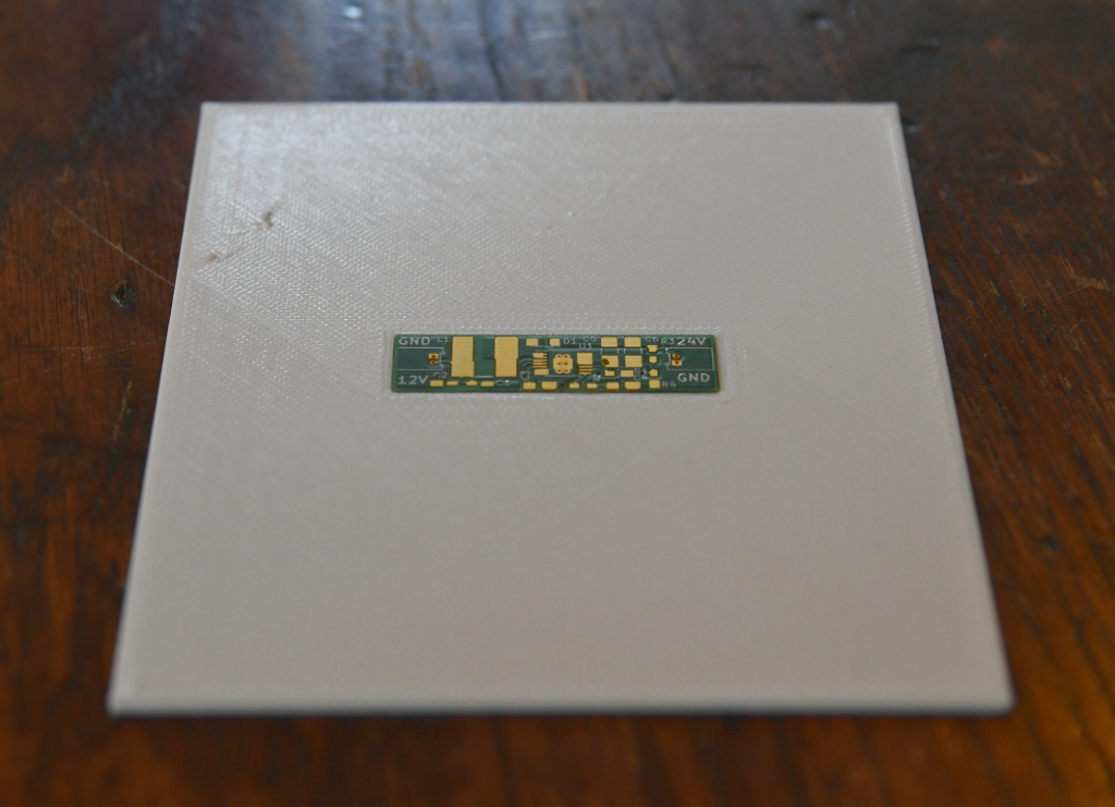
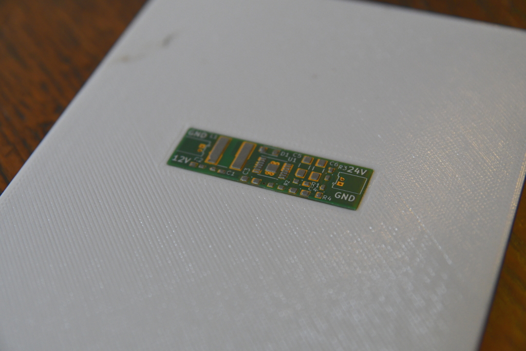
The PCB in the holder:
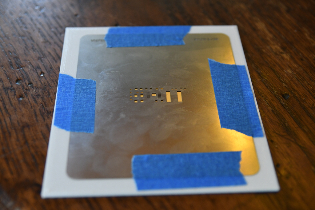
The stencil taped to it:
Paste on stencil:
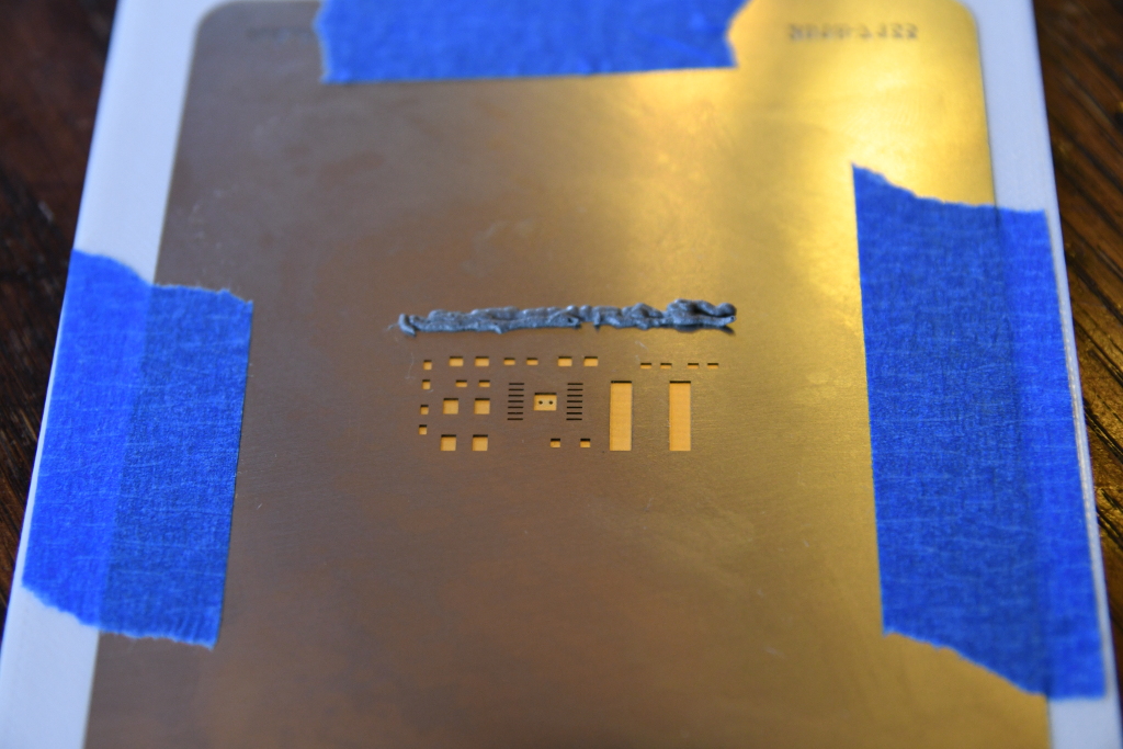
Paste applied:

Stencil removed:
Components placed:
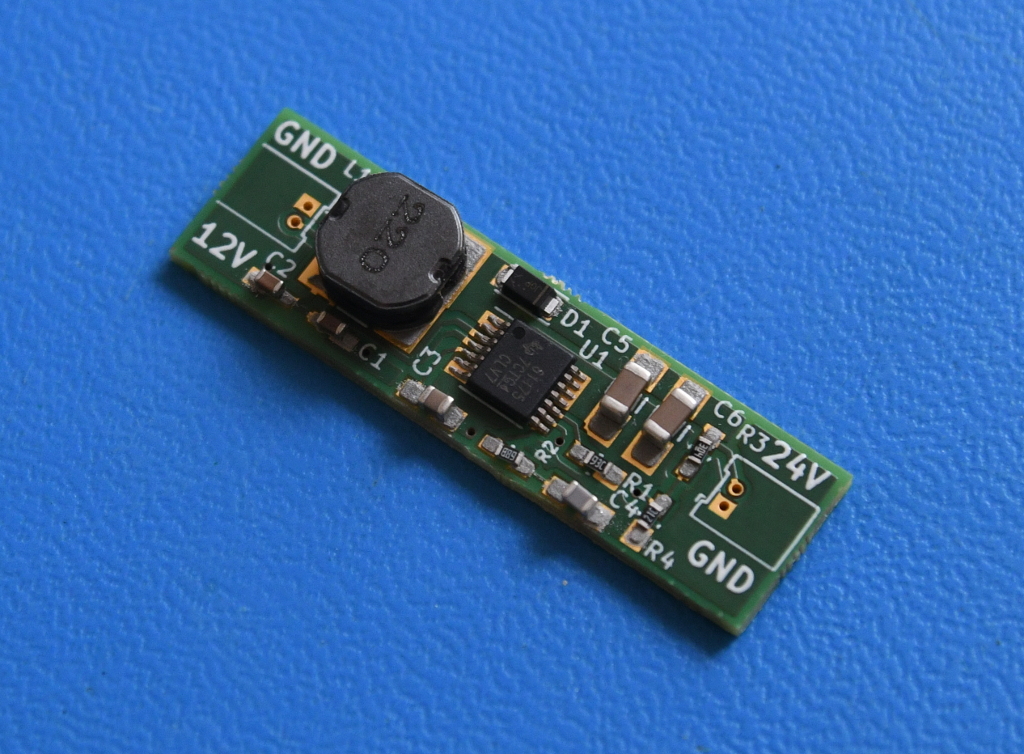
Reflowed in the oven:
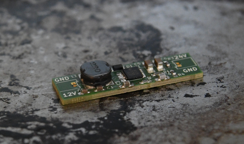
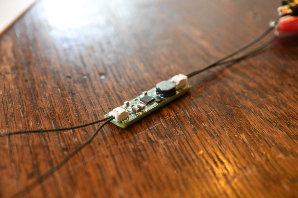
Conclusion
Using the 3D printed jig worked good. The board under test: